Now the Walls — Climate-Wall™
One Climate-Wall™ Panel Replaces Twelve Layers
That was Climate-Deck™, the floor system. This is the wall — the same panel logic stood vertical. The industry’s own forming systems shape the wall — our patented cast-in ties arm it. It is the most energy-efficient thermal-mass construction we know how to build, with the arithmetic behind it.
STANDARD PARTY WALL
fire + sound between attached units — published assembly
1. Gypsum panel (finish)
2. 2x4 stud framing + sound batts
3. Gypsum panel
4. 1" gypsum liner panels
5. 2" H-studs 24" o.c. + C-runners
6. Aluminum breakaway clips
7. 3/4" mandated airspace
8. Fire blocking — two levels
9. 2x4 stud framing + batts
10. Gypsum panel
11. Cavity spray foam — bridged every 16"
12. Siding / finish layer
12 LAYERS. SIX CREWS.
And after all that, it’s only the wall between units — the outside walls are a whole separate build
STANDARD EXTERIOR WALL
typical cold-climate frame wall — one stud row
1. Siding / finish layer
2. Housewrap / WRB
3. OSB sheathing
4. 2x6 studs 16" o.c. + cavity insulation — PICK ONE:
R-21 fiberglass battscavity R-21 → ~R-16 delivered
Open-cell foam, full 5.5" fillcavity ~R-20 → ~R-16 delivered
Flash & fill: 2" closed + 3.5" opencavity ~R-26 → ~R-18 delivered
Closed-cell foam, full 5.5" fillcavity ~R-35 → ~R-21 delivered
5. Vapor retarder
6. Gypsum panel + finish
EVERY OPTION HITS THE SAME CEILING
Fill the cavity with anything — the studs bridge it every 16". Best case, full closed-cell: ~R-21 delivered
CLIMATE-WALL™
one panel — the industry’s forms shape it, our cast-in ties arm it; serves party AND exterior; exterior config shown
3/4" U-Stucco™ — the finish IS the cladding · insulated stuccoR-1.7
2" closed-cell foam — continuous, unbroken · IS the vapor + air barrierR-12–14
4" concrete — structure + fire + sound + massR-0.3
4" open-cell foam — continuous + acousticR-14–15
3/4" U-Stucco™ — in lieu of drywall · insulated stuccoR-1.7
ONE PANEL · FOUR TRADES
Pour the core & set the hardware → thread the studs → spray the foam → trowel the U-Stucco™. Replaces both assemblies.
~R-31 delivered, zero bridging — U-0.032 where code allows U-0.060
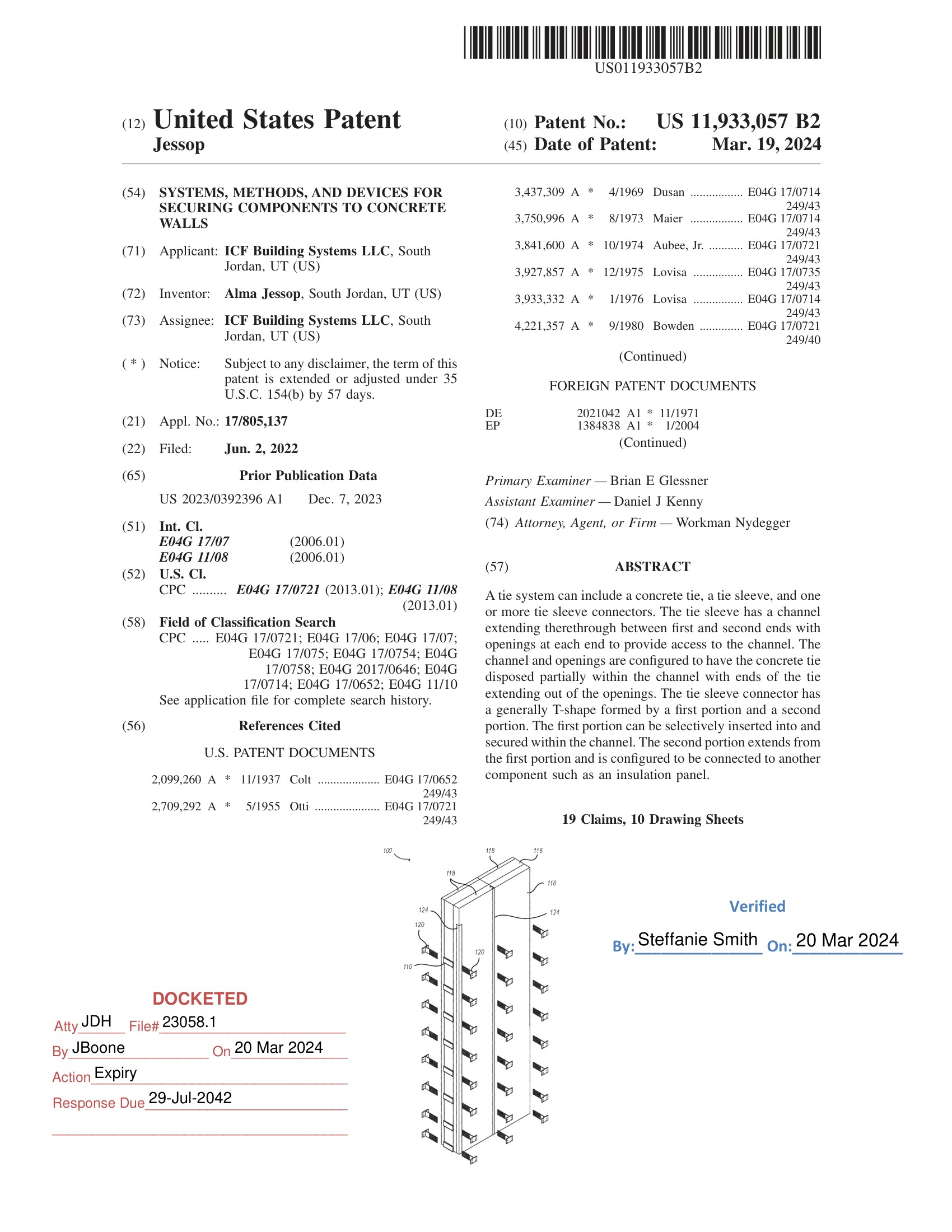
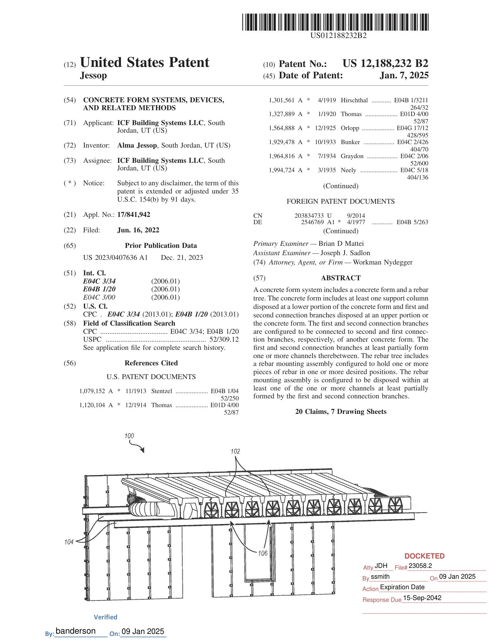
ClimateBuilt™ · Climate Tech Building Systems · climatebuilt.com · U.S. Patents 12,188,232 B2 & 11,933,057 B2 · U-Stucco™ R-value per manufacturer’s published R-2.2/inch (ustucco.com)
The formwork — two patents, two stories. Be specific.
FLOORS & ROOFS — our form IS the patent. The CD family (CD-18 · CD-24 · CD-24CF) is a wire-cut EPS concrete form — cut from stock billet at a local foam shop, no molds — that stays in place as the insulation after the pour and arrives carrying its own rebar retention hardware. That is the invention: “Concrete Form Systems, Devices, and Related Methods” (US 12,188,232 B2).
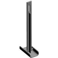
WALLS — the industry’s forms are the freeways; our ties ride them. The aluminum forming systems and the steel forming systems that pour America’s walls are already built, already on every jobsite — the freeways and highways of concrete. The patented ties (US 11,933,057 B2) are cut to run on them: one tie profile for the aluminum systems, one for the steel systems — two profiles, and the removable-forms market is covered. We don’t replace their forms. We arm them.
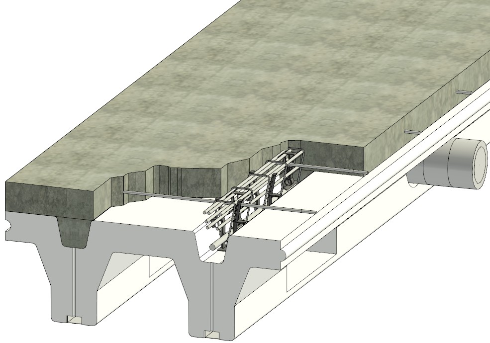
CD-18 cutaway: the white wire-cut EPS form stays in place under the finished deck — formwork and insulation are the same part.
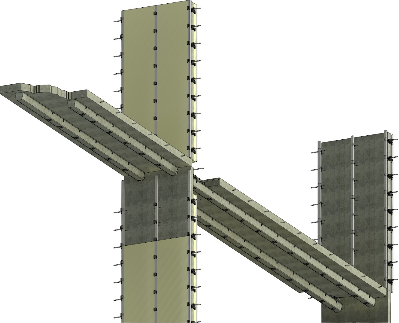
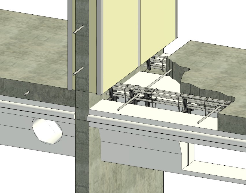
Deck junction: the cream EPS under the panels is the form — it never strips, it insulates.
NOW THE FLOOR — CLIMATE-DECK™
Same workup, horizontal. CD-18 / CD-24 / CD-24CF are concrete FORM systems — the panel is cast in its form, and the form stays as the insulation. Residential floor shown; the commercial tilt-up roof below.
STANDARD FRAMED FLOOR
1. Finish flooring
2. 1.5" gypsum-concrete topping
3. Acoustic mat
4. 3/4" subfloor
5. Floor framing + cavity insulation — PICK ONE:
2x10 joists 16" o.c. — R-30 battscavity R-30 → ~R-26 delivered
2x12 joists — R-38 battscavity R-38 → ~R-32 delivered
9-1/2" TJI (standard) — R-30cavity R-30 → ~R-27 delivered
14"–16" TJI — R-38cavity R-38 → ~R-34 delivered
Open-web floor trusses to 24" — R-38 drapedcavity R-38 → ~R-31 delivered
6. Resilient channel
7. Gypsum ceiling board
EVERY DEPTH, SAME STORY
Joists and webs bridge every option — and the ducts still hang below it in a drop ceiling. Commercial framed floors buy their sound rating back with a gypsum-concrete topping over acoustic mat, on top of everything above.
Delivered values: cavity R degraded by the framing factor (~10% dimensional lumber, ~6% TJI webs)
CLIMATE-DECK™ — RESIDENTIAL
Finish floor — direct to slab
5" concrete slab — structure + fire + sound + massR-0.4
5" continuous 2-lb EPS — full depth except above the 23"×11" trunk & 10" round openings~R-21
Ceiling — infill panel or open plenum, your call
Radiant floor option: 1½" EPS + 1½" gyp-crete pour (radiant tubing in the pour) over the slab — wood glues down, tile thin-sets, right on the gyp-crete
Precast without the 2-lb foam: hang the ceiling joists, spray 2" open- or closed-cell under the lid before mechanical — then drywall on the metal joists, or an acoustical ceiling
ONE PANEL
~R-21 continuous under the slab · ducts run INSIDE the depth · no drop ceiling
2-lb EPS at published ~R-4.2/inch
The commercial roof — CD-24CF tilt-up.
Designed to span 50’ bays. The EPS tapers to a maximum 2½" on half of the 18" beam — on purpose: the taper opens a welding-helmet-sized bay so the welder can get his head up in there, see the joint, and weld the 6"×6" angle iron to the tilt-wall embed plate.
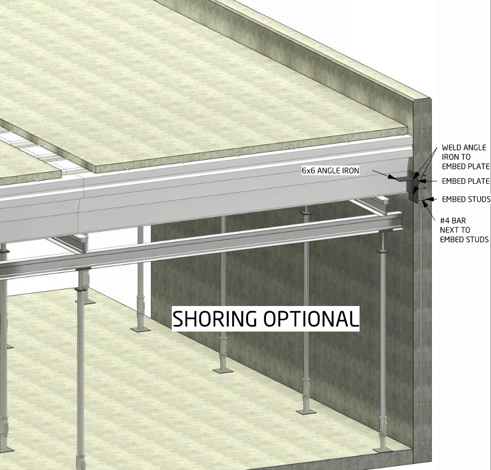
From the CD-24CF system drawings — shoring optional. Consult your structural engineer for project specifications.
The load path.
Four #7 bars and one #8 land in the center of each concrete beam. Every section transfers its load from the beam’s center out to the 6"×6" angle iron at the opening — documented across the CD-24CF detail sheets and the SD-100 structural calc series.
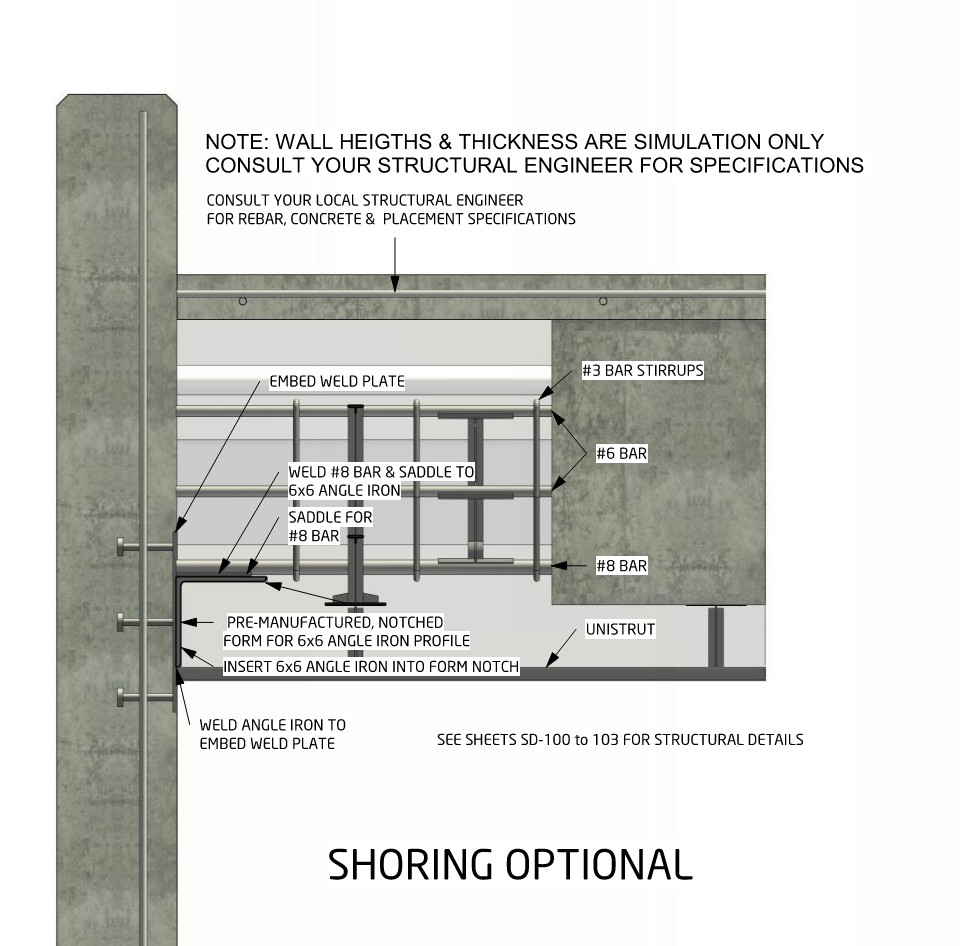
Load-transfer cross section from the CD-24CF sheets — see SD-100–103 for structural details. Consult your structural engineer for project specifications.
The rebar retention system — cast into the form.
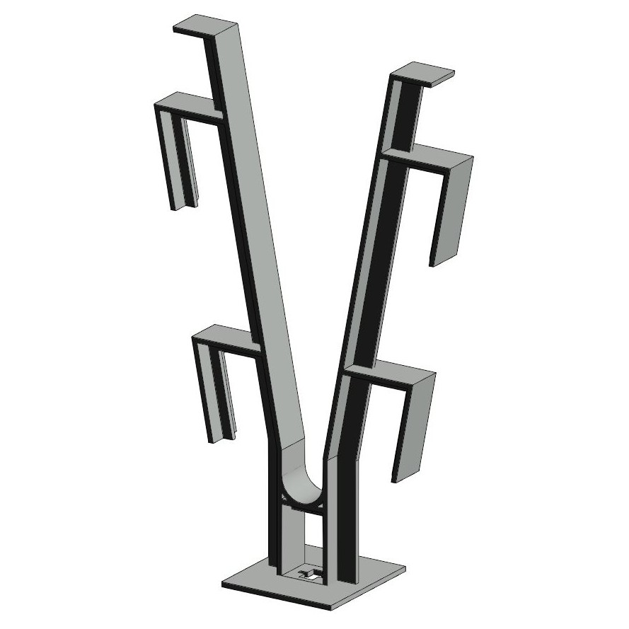
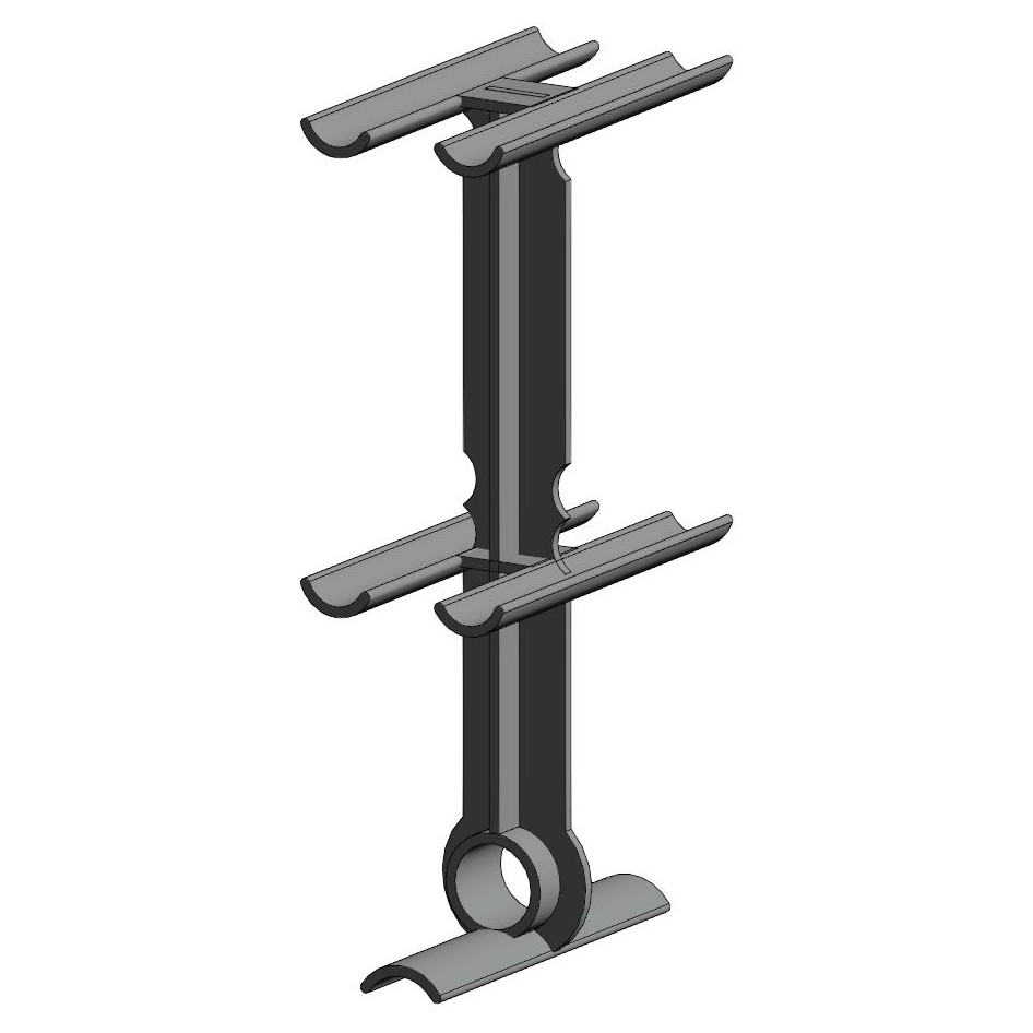
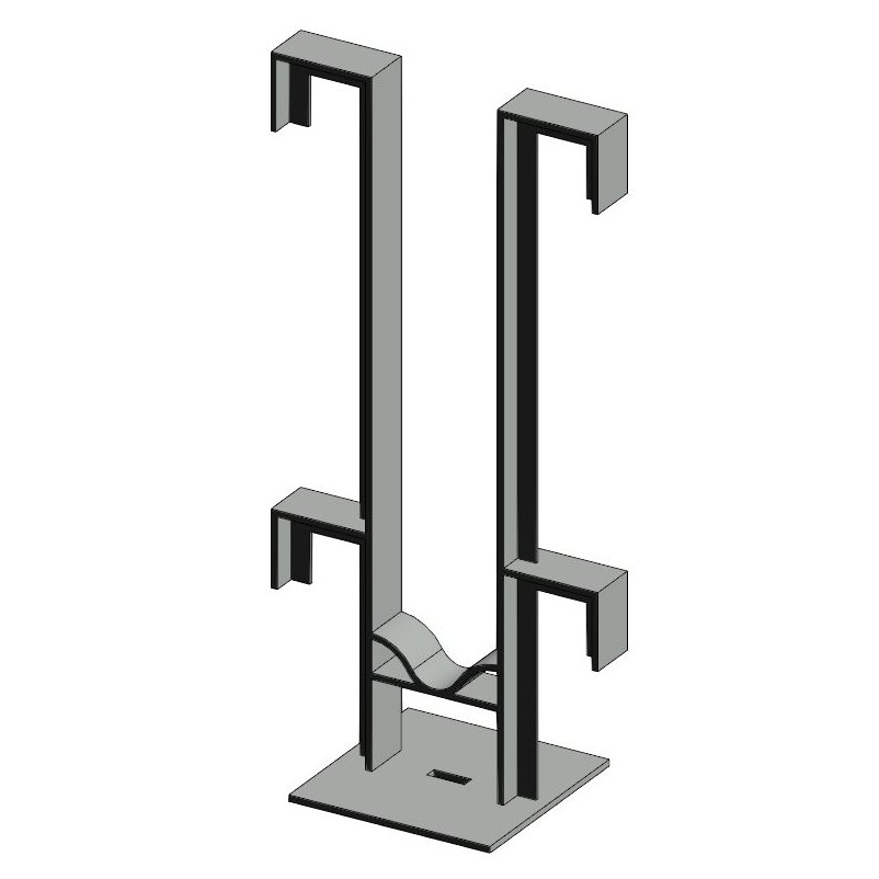
Three form families — CD-18 (24’ span), CD-24 (36’ span), CD-24CF (50’ commercial tilt-up) — and each carries its own rebar retention hardware, placed before the pour: the rebar tree holds the beam cage, the rebar chair seats the bars at depth, the vertical tie rides the form edge. The bars land in the saddles — the placement is in the hardware, not in a tape measure.
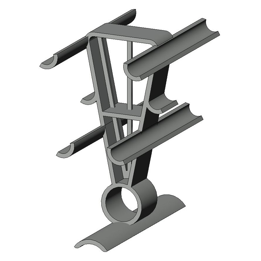
CD-18 · rebar tree
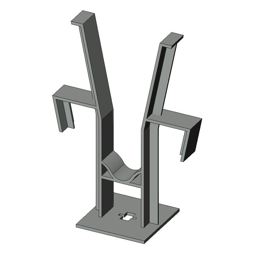
CD-18 · rebar chair
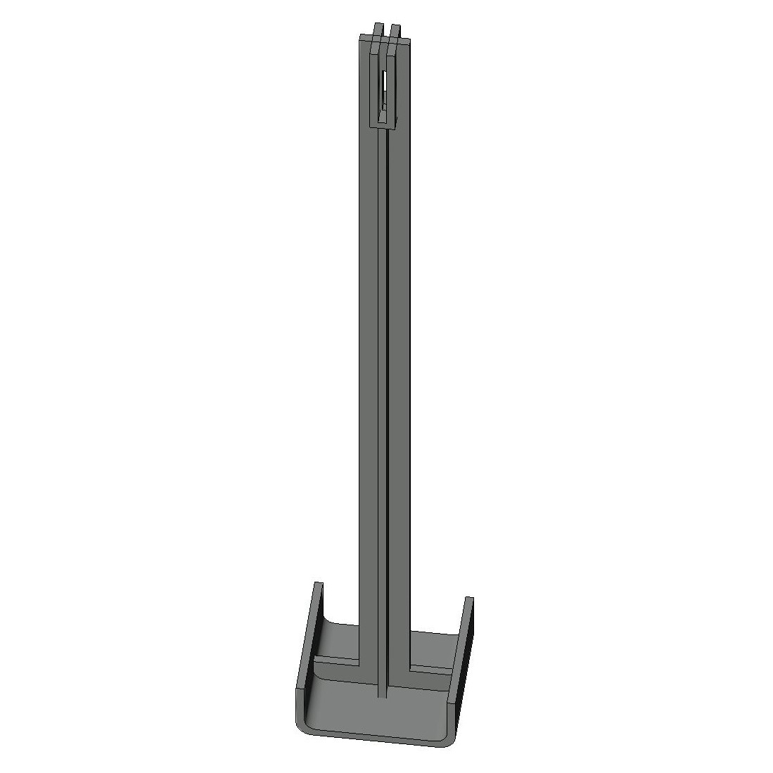
CD-18 · vertical tie
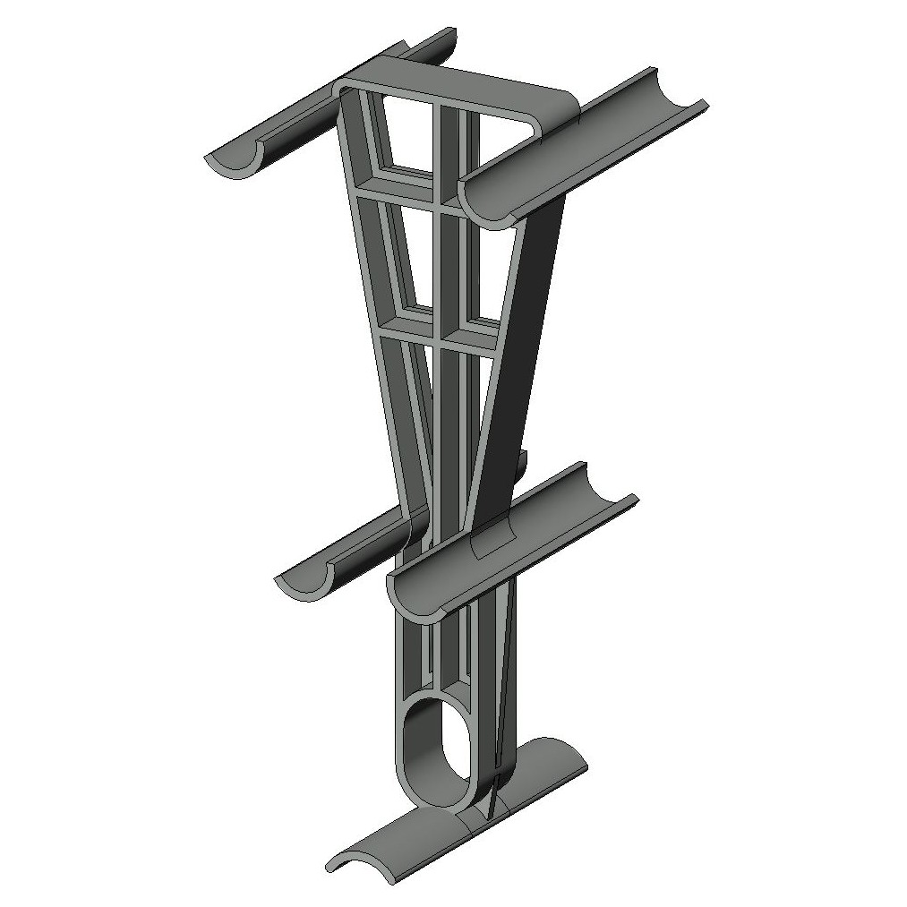
CD-24 · rebar tree
CD-24 · rebar chair
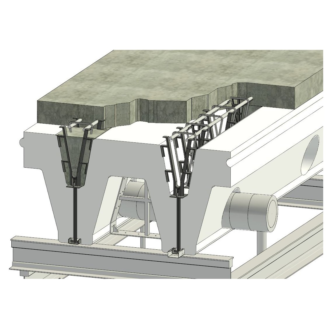
CD-24 · in the form
CD-24CF · rebar tree
CD-24CF · rebar chair
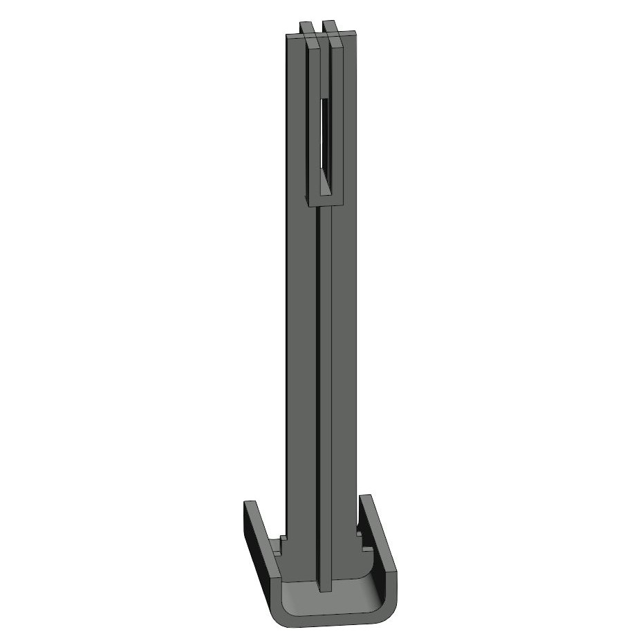
Vertical tie · ¾" strut
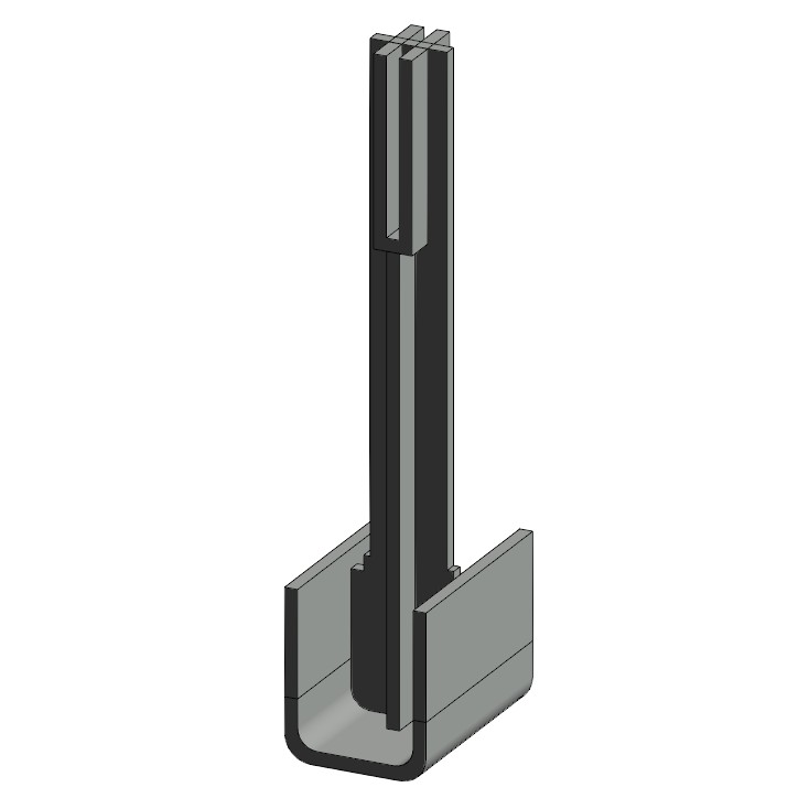
Vertical tie · 1½" strut
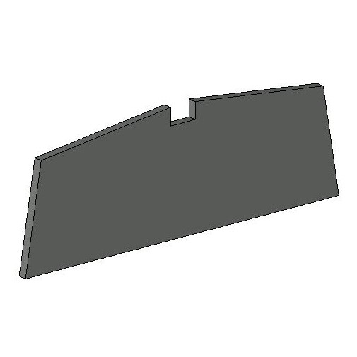
The pin wedge · all three systems
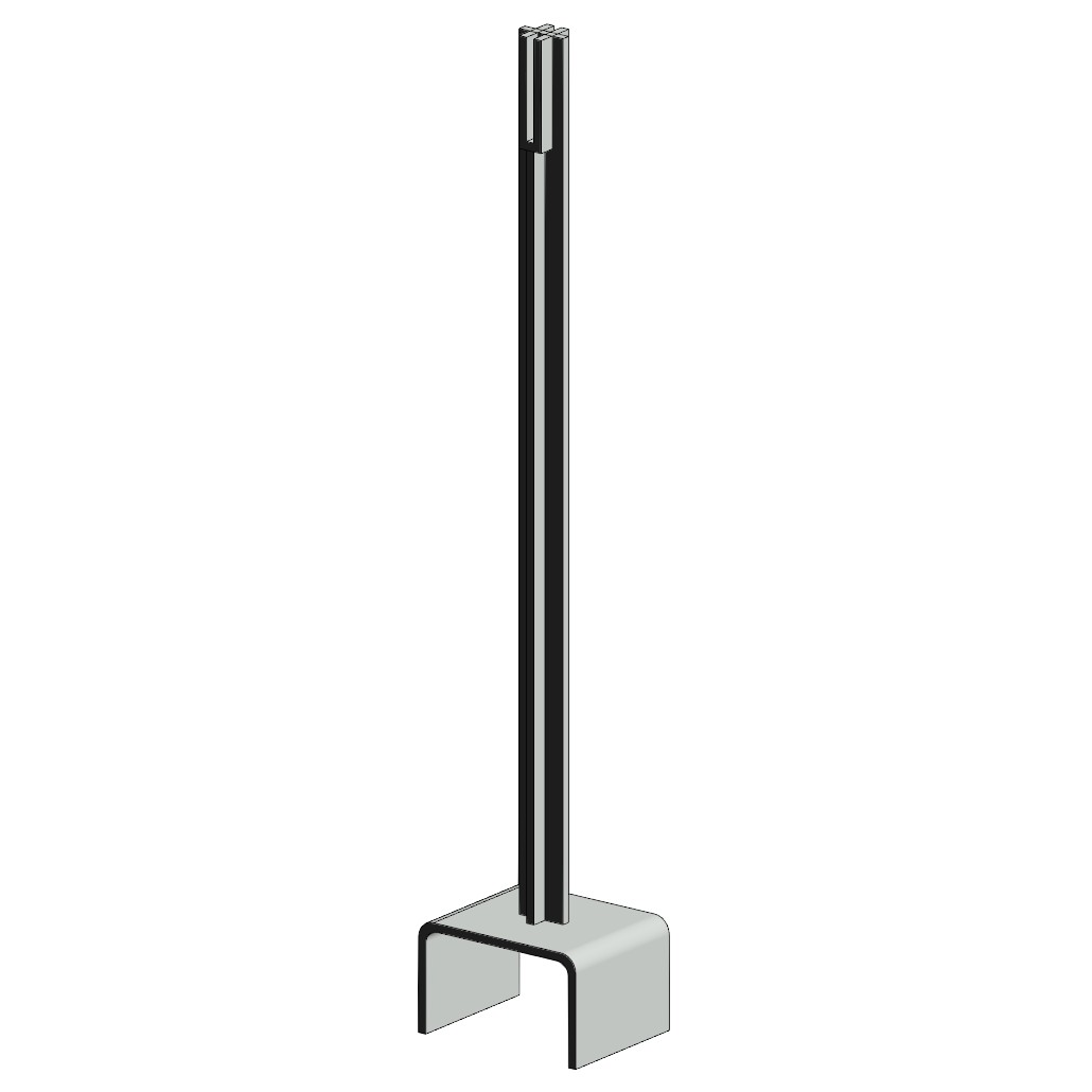
Vertical tie · AAC / lumber (inverted U)
Renders from the CD-18 / CD-24 / CD-24CF system drawings. One pin wedge serves all three floor systems. Consult your structural engineer for project specifications.
~R-31 DELIVERED
Continuous foam + insulated stucco both faces, zero thermal bridging. A code frame wall delivers ~R-16 after the studs bridge it.
U-0.032 vs U-0.060
A cold-climate (IECC Zone 6) code frame wall is allowed U-0.060. Climate-Wall™ lands almost twice as far past the code line.
+2" CONCRETE = +0.5% R
4" vs 6" wall, same foam: R-28.9 vs R-29.1. Concrete is the structure. Foam is the R.
NEARLY HALF THE R OUTSIDE
Closed-cell + insulated stucco out, open-cell in — dew-point safe for cold climates. The split flips by climate zone.
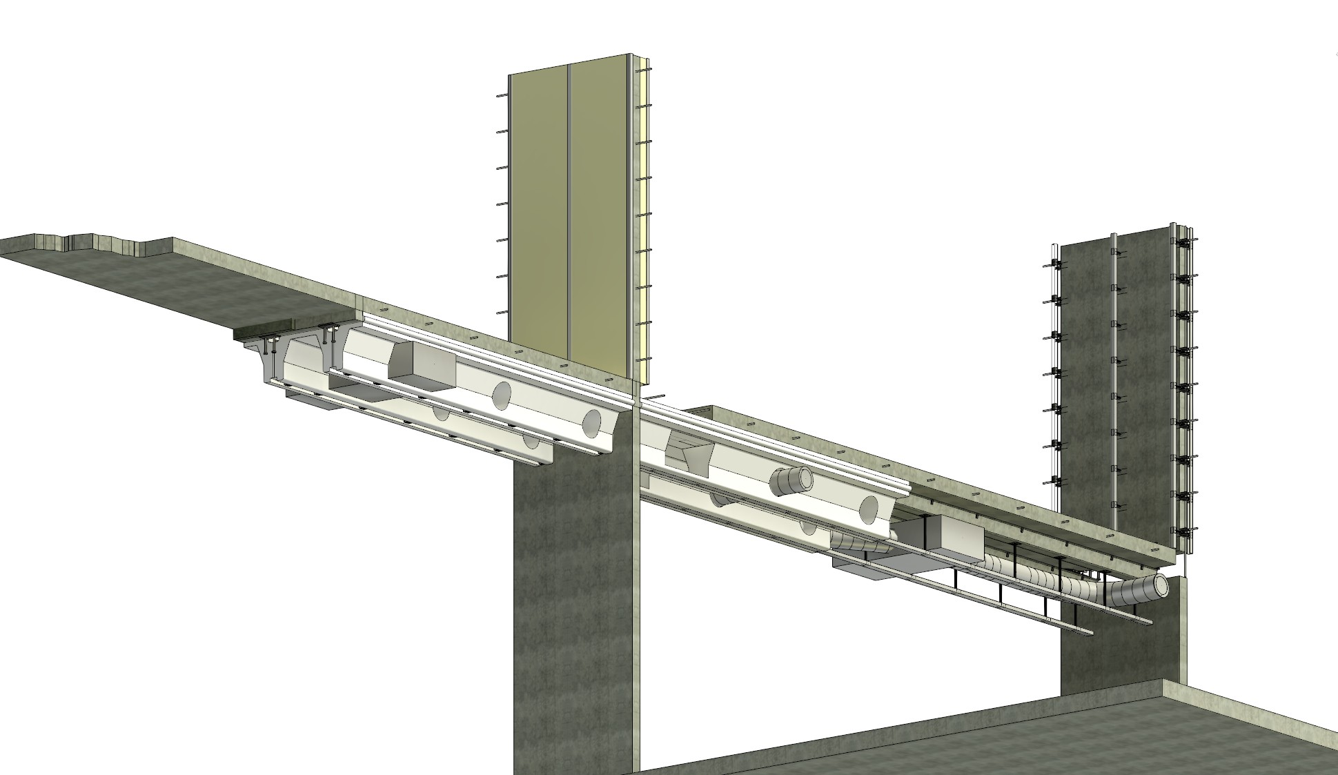
The whole build in one section: precast panel at right · wire-cut foam forms · party wall · insulated second floor already in place · steel-stud wall and ceiling framing threaded onto the cast-in hardware. Crane the slabs onto the walls, weld them down, keep going — then skin it and call it good. Not a stick of lumber anywhere in this drawing.
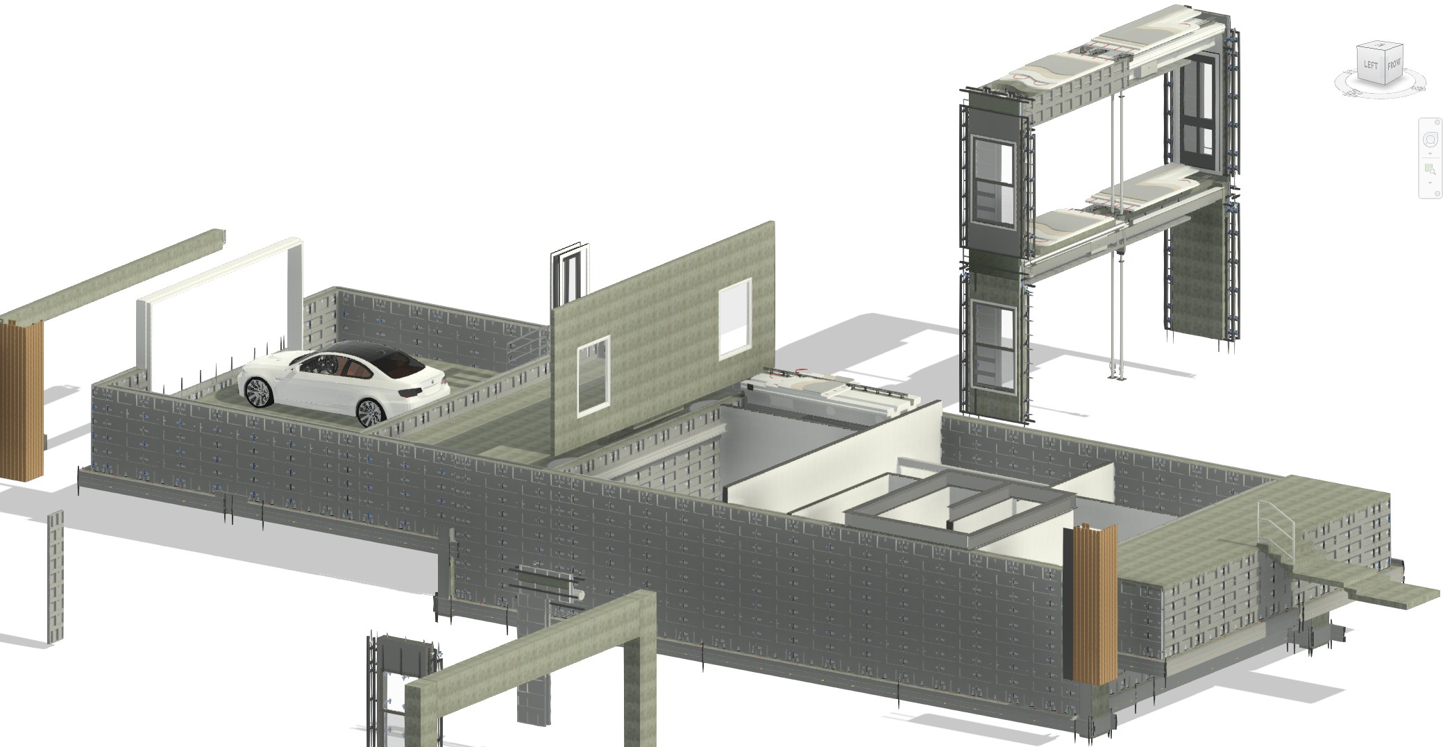
And the jobsite, mid-build: the industry’s forming panels standing on the walls with the tie spikes running the top of every pour · AAC double-framed window and door openings ready for standard flanges · finished panels beyond · floor and window assemblies stacked and waiting for the crane. Every piece on this page, in one model.
Same foam. Sprayed where it works.
Standard practice foams the cavities between framing — a thermal bridge every 16 inches. Climate-Wall™ sprays the outside: one continuous blanket, the concrete mass inside the envelope working as a thermal battery. Same crews, same rigs, no retraining — the yellow in every render is the foam.
Dried in the day the crane leaves.
MOUNT HARDWAREATTACH STEELMECHANICALINSPECTINSULATE
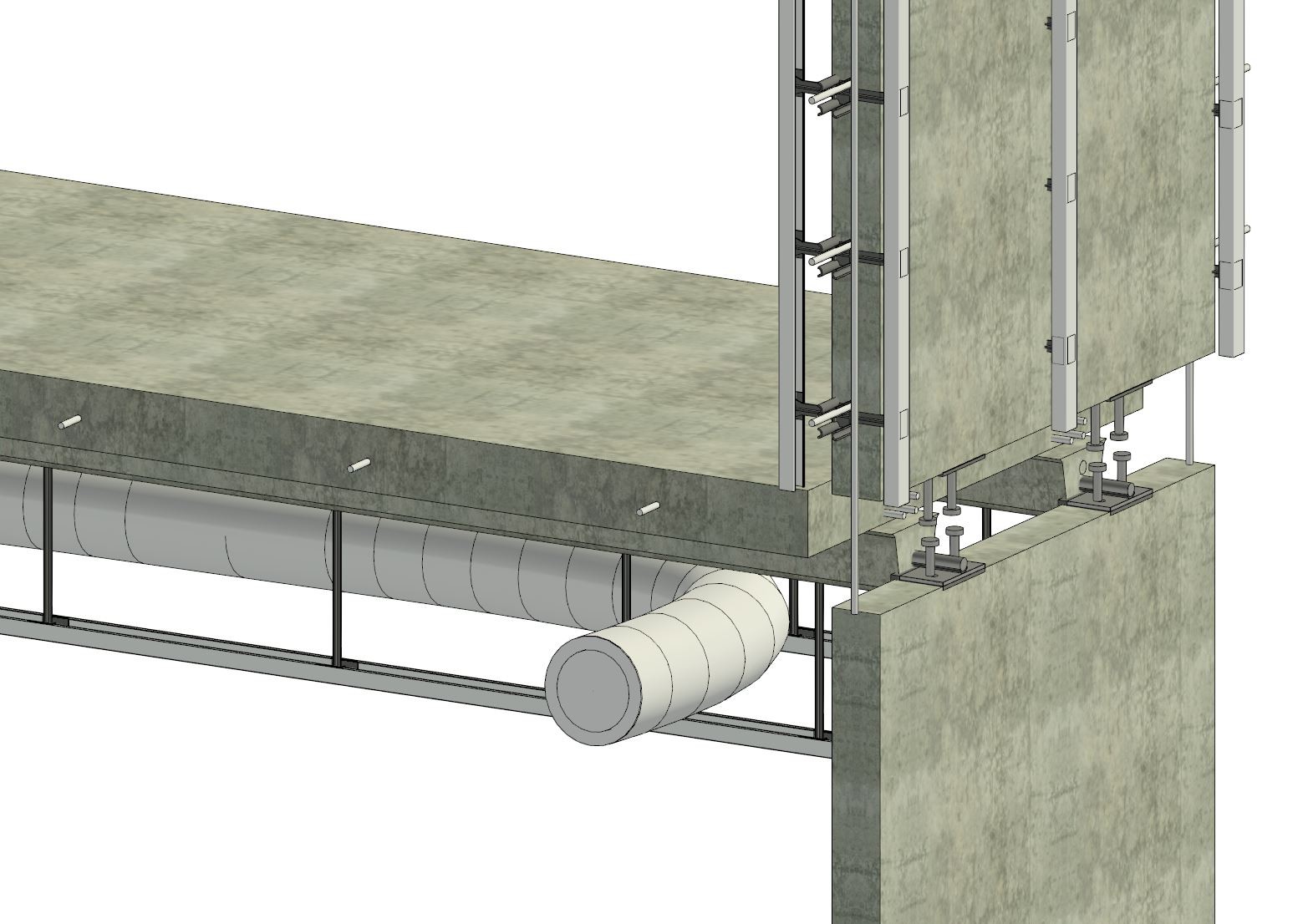
Precast or cast-in-place — same steps: mount the hardware, attach the steel stud & ceiling members, run mechanical, inspect, and insulate. No lumber package, no dry-in race, no batts threaded around trusses.
Their factory vs. our wire.
Competitor ICF blocks: steam-chest molding plants, a mold per SKU, millions in tooling — then freight on blocks that are 98% air, shipped across states.
Climate-Deck™: its EPS form is hot-wire cut from stock billet at a local foam shop within 50–100 miles of nearly every job in America. No molds. No factory. A cut file.
Climate-Wall™ needs no foam shop at all: ready-mix concrete, embedded core hardware, spray-applied foam — every input already local, nothing cut, nothing shipped.
And the mix is chemistry-agnostic — low-carbon mixes from suppliers like CarbonCure, CarbiCrete or Blue Planet drop straight into the same panel.
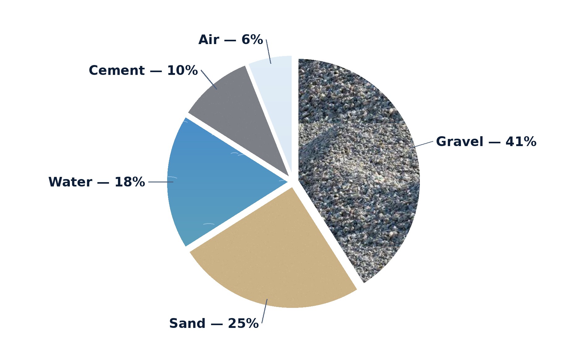
~84% of ready-mix concrete is rock, sand and water — sourced within miles of the job.
Concrete doesn’t burn. Neither does the finish.
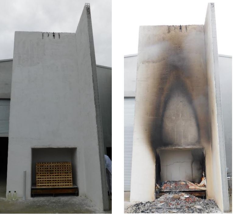
U-Stucco™’s own burn test on a U-Stucco™-finished panel — scorched at the surface, standing when the fire is ash. Their published spec: withstands 3,000°F+ for 2+ hours, Class A1, without igniting, smoking or spreading flame. No assembly of liner panels, clips and blocking trying to buy back fire resistance — the materials themselves are the rating.
Solid beats the grid.
Same wall, three concrete geometries — from the CTBS engineering workbook. The solid panel carries ~19% more concrete than a waffle grid and ~23% more than a screen grid: full mass, full strength, full fire and sound, no thin webs between cores. Grid ICFs use less concrete on purpose — and give up exactly that much wall.
And the wood frame wall is the whole point. Run the mass math, per square foot of wall:
2×4 framed wall — studs, sheathing, gypsum, siding, batts≈ 9 lb/SF
2×6 framed wall — same build, deeper cavity≈ 11 lb/SF
4" solid concrete — 150 lb/CF × 4/12 ft= 50 lb/SF · ~5½× the 2×4
6" solid concrete — 150 lb/CF × 6/12 ft= 75 lb/SF · ~7× the 2×6
Under lateral load — wind, seismic, the storm below — a framed shear wall works through the nails in its sheathing, rated in the code tables at a few hundred pounds per running foot, and cycling works those nails loose. A reinforced solid concrete wall resists through the whole monolithic section, engineered capacities an order of magnitude higher, with the mass and the continuous load path to hold down what the wind tries to lift.
Any core. Any insulation depth. No molds.
The ICF market standardizes on 6" cores; its 4" blocks are the restricted product — above-grade only, height-capped, still a molded block. Climate-Wall™ is a solid poured wall at any core — the hardware scales instead: a nominal 3½" wall takes the 4" core hardware, a 5½" wall takes the 6", and up from there.
The insulation side scales the same way — the wedge length follows the thickness the architect specifies: a 3½" wedge carries 2" of spray foam, a 5½" wedge carries 4", interior or exterior. No other system can do that. And it’s always spray-applied — sheet goods on a wall are logistics and cost for nothing. A hardware size, not a tooling line.
Grid-vs-flat characterization per ICF industry trade references; mass figures from the CTBS engineering workbook; per-SF weights and shear characterizations are typical published values — capacities are project-specific, consult your structural engineer.
One serrated spike. Any anchor head.
The patented tie family bends and adapts to the geometry of the anchoring system you want — same cast-in serrated spike, different head. Want a stud on the interior? The saddle head carries an AAC stud — or slides 1½" treated timber straight in when lumber is the last resort. Want steel? The channel head threads a 1½"×1½" metal stud on. A flat T-plate, a masonry tie — one system, every anchoring geometry. And it adapts to the forming system too: the ties are cut for aluminum forming systems, with a sibling profile for the other major removable-form brands — same concept, resized to the form.
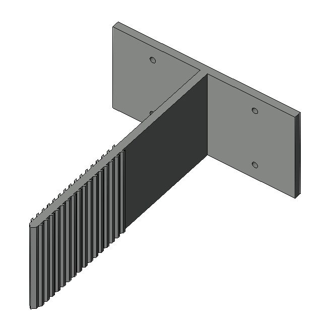
Exterior flat T-tie · 90° California corner
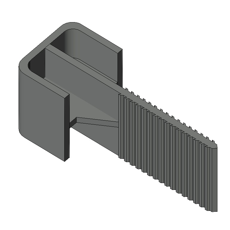
Metal stud 1½"×1½"
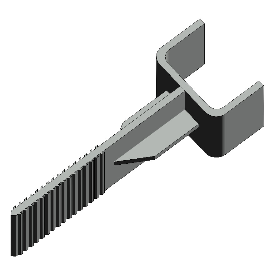
AAC / treated lumber stud
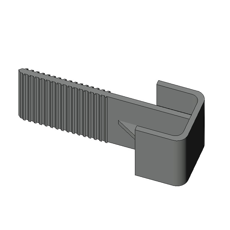
AAC stud · aerated autoclave concrete
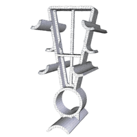
And the ties are a SYSTEM. The center tie holds the T-tie spikes from the exterior and interior faces — its interior is the zip-tie technology, serrated banks that grab the spike and hold. The center tie with post is the anchor point: set two corner-post center ties and the corner tie loads into them, closing the corner. And the flat T-plate builds almost anything — including the 90° California corner.
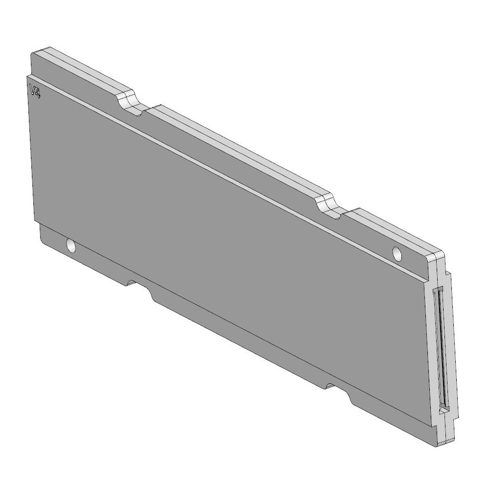
Center tie
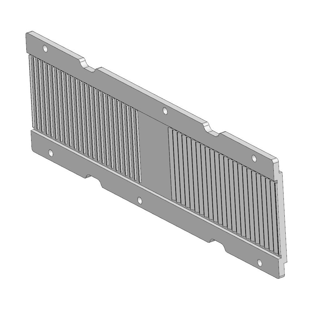
Inside: the zip-tie technology
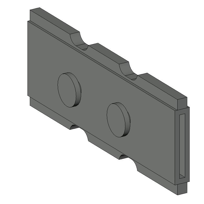
Center tie with post
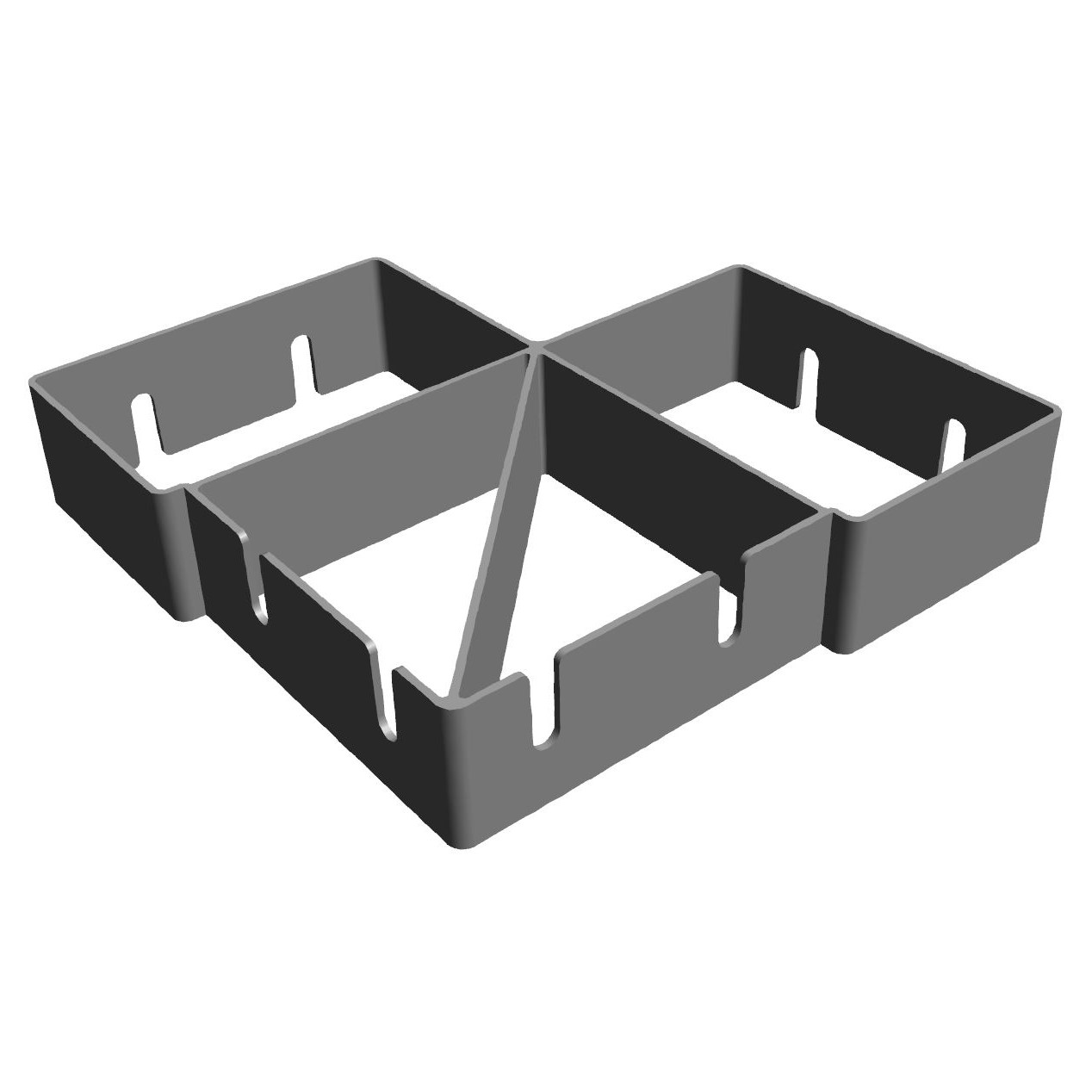
The corner tie
And the question everybody asks — windows and doors: every opening is double-framed with aerated autoclave concrete. The first AAC frame goes inside the foundation wall forms; the second frames out the width of the interior and exterior insulation. The result: AAC window and door openings you can screw a standard window or door flange straight into. Case closed.
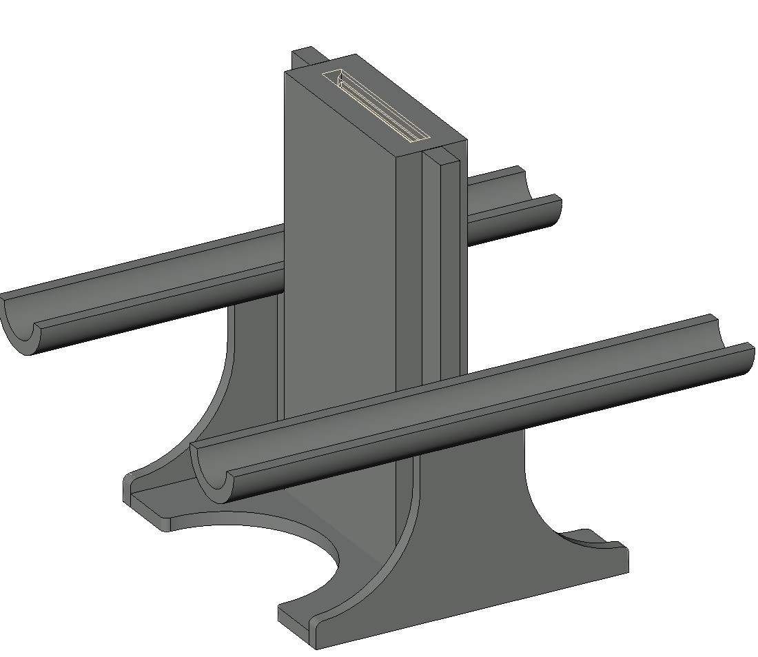
And the same family does precast: the saddle heads carry the rebar in the panels that go into tilt walls.
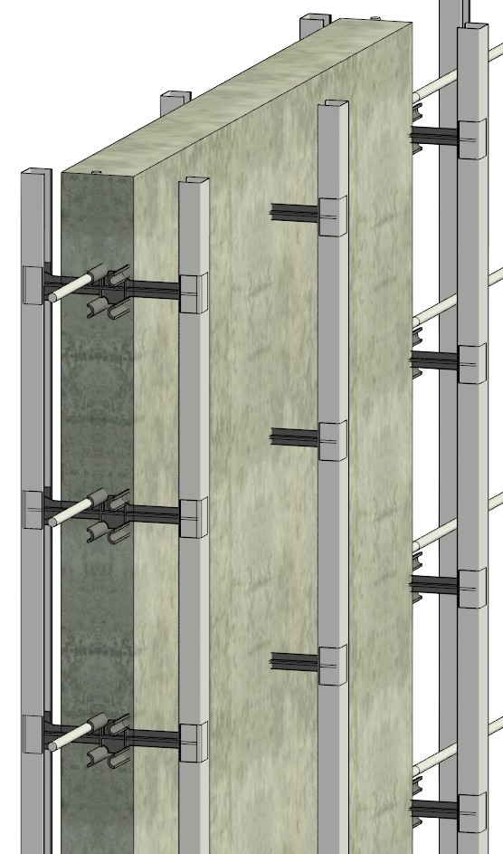
The assembly: ties through the panel, studs threaded on both sides — cast flat, tilted up.
Product renders from the CTBS hardware library — U.S. Patents 12,188,232 B2 & 11,933,057 B2.
WHEN THE STORM COMES, THE DIFFERENCE ISN’T SUBTLE.
Hurricane Michael, Mexico Beach FL, 2018: one reinforced-concrete house stood essentially intact while the wood-framed neighborhood around it became debris. The press called it the “Sand Palace.” Concrete walls, elevated structure, continuous load paths — the same physics Climate-Wall™ delivers, cast at a precast shop or on-site. Same panel, same rating, either way.
Widely reported — The New York Times, ABC News and others, October 2018. Background: Hurricane Michael →
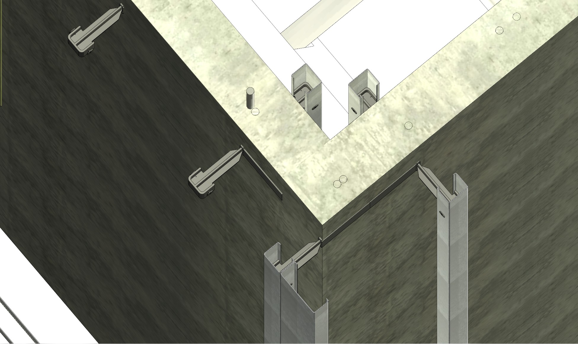
Look straight down into the corner: the spikes seat into the cast-in hardware, the metal stud threads on, and two panels close into a California corner.
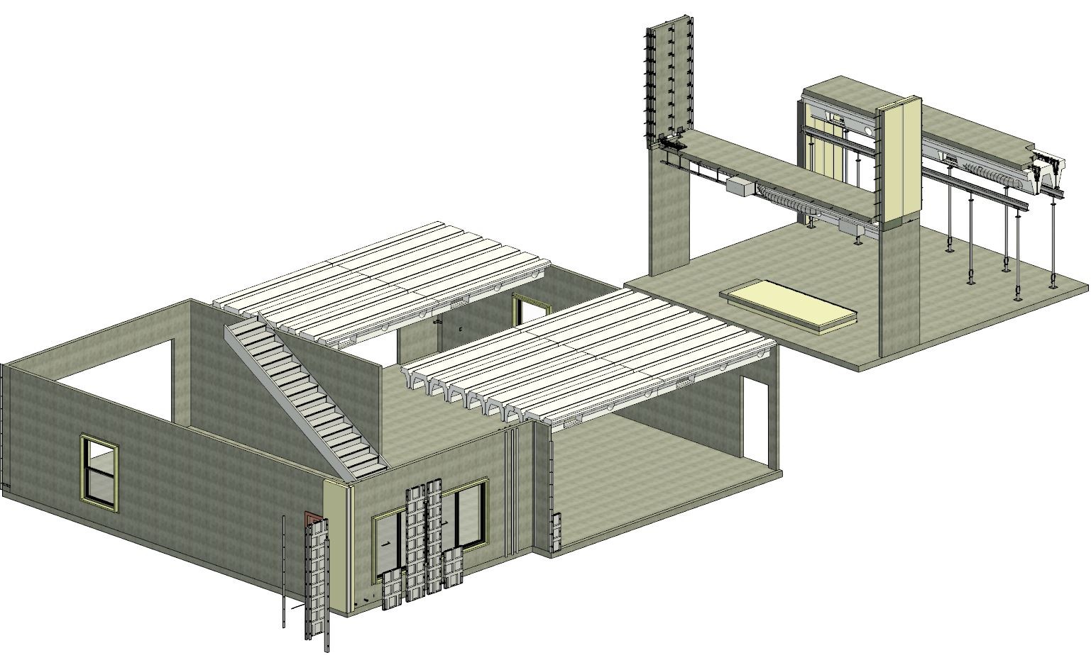
One casting station. Walls, decks, roofs — poured flat, craned to plane. The whole house comes off one table.